Diagnosing Marine Electrical Faults with a Multimeter


Marine electrical problems can range from a navigation light that suddenly stops working to a battery that repeatedly goes dead. Finding the cause is often more useful than simply replacing the failed component. A digital multimeter can help boaters locate many common electrical faults by measuring voltage, resistance and continuity.
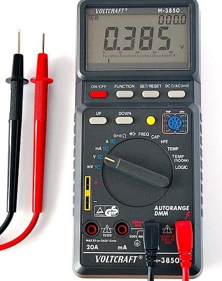
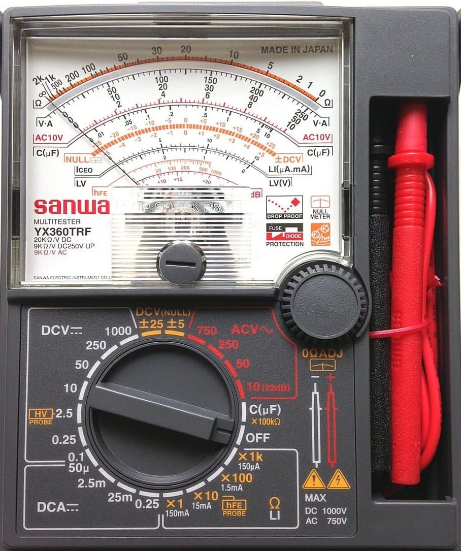
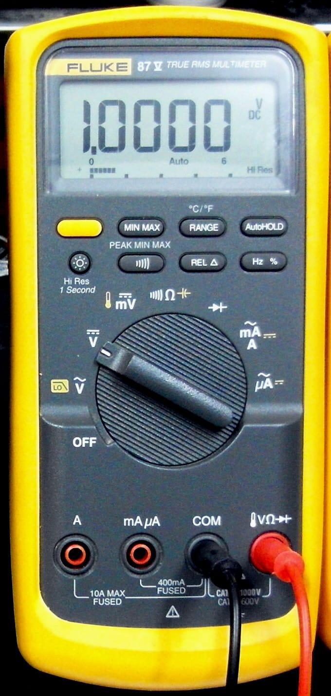
A multimeter measures different kinds of electricity in batteries, wires and electronic parts. It combines three tools: a voltmeter, an ammeter and an ohmmeter. Used correctly, a multimeter can determine whether power is reaching a component, whether a circuit is complete and whether excessive resistance is causing a voltage drop.
Before beginning any electrical troubleshooting at the marina or private boat dock rental, turn off power to the circuit when appropriate and understand the limitations of the equipment being tested.
Understand the Circuit First
Before picking up a multimeter, identify the circuit and understand how power is supposed to travel through it. A typical 12-volt DC boat circuit includes a battery or other power source, positive wiring, a fuse or circuit breaker, a switch, the load and a return path to the negative bus or battery negative.
A wiring diagram can be particularly useful. Trace the circuit from the power source toward the component and then back to the negative side. Corroded connections, loose terminals, damaged wires and failed switches can interrupt power even when the component itself is functioning properly.
Marine environments add another complication. Moisture and salt can accelerate corrosion at terminals and connections, increasing electrical resistance. A connection may look intact while still causing a significant problem. Check for issues like this while working on circuits at a private boat slip for rent, marina or your driveway.
Start With a Voltage Test
Voltage testing is often the best starting point for a circuit that is not working. Set the multimeter to measure DC voltage and select a range appropriate for the boat's electrical system. On a typical 12-volt system, the meter should be connected in parallel with the circuit or component being tested.
Begin at the power source. Measuring directly across the battery terminals provides a reference for the voltage available to the circuit. Then work progressively downstream, checking points such as the fuse or circuit breaker, switch and load.
If voltage is present on one side of a fuse but absent on the other, the fuse or its connection may be the problem. If voltage reaches a switch but does not leave it when the switch is turned on, the switch or its terminals may be faulty.
This step-by-step approach can narrow the problem to a specific section of wiring rather than requiring replacement of multiple components.
Check for Voltage Drop
A circuit can show apparently normal voltage when measured with little or no load but still perform poorly when the equipment is operating. Voltage-drop testing helps identify unwanted resistance in the circuit.
With the load operating, measure the voltage at the component and compare it with the voltage available at the power source. A significant difference indicates that some voltage is being lost along the circuit.
Check both the positive and negative sides. A corroded positive connection can cause voltage loss, but so can a poor negative connection. This is particularly important on boats because a faulty return path can produce symptoms that resemble a failed component.
Voltage-drop testing is especially useful for circuits powering equipment such as pumps, motors and other higher-current loads.
Test Continuity With Power Off
Continuity testing can determine whether electricity has a complete path through a wire, fuse, switch or other component. Before performing a resistance or continuity test, disconnect power from the circuit. Measuring resistance on an energized circuit can damage the meter and produce misleading results.
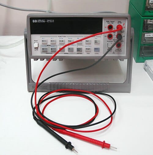
Set the multimeter to its continuity or resistance setting. Touching the meter probes together should produce a very low resistance reading or, on many meters, an audible tone. This provides a quick check that the meter and test leads are functioning.
A wire that should be continuous but produces an open-circuit indication may be broken or disconnected. A switch can also be tested by checking whether its terminals change from open to closed as the switch is operated.
Remember that continuity alone does not prove that a circuit can carry its required current. A damaged or corroded connection may show continuity while still having enough resistance to cause a problem under load.
Investigate Unexpected Resistance
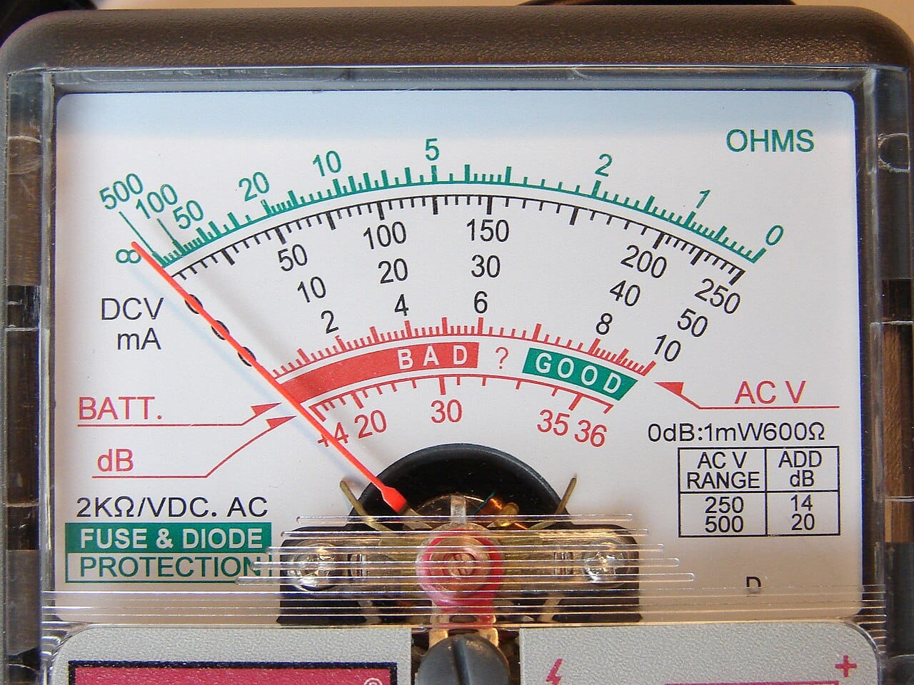
Resistance measurements can help locate certain electrical problems, particularly when power is disconnected. An unexpectedly high resistance in a wire or connection can indicate corrosion, a poor crimp, a damaged conductor or another connection problem.
Resistance testing can also help evaluate some electrical components, although the correct resistance depends on the component and its design. Always compare the reading with the manufacturer's specifications when available.
Don’t assume that a low-resistance reading automatically means a component is good. Some components can’t be meaningfully diagnosed with a basic resistance test, and electronic equipment can require specialized testing procedures.
Test Fuses and Connections
A blown fuse is sometimes the symptom rather than the cause of an electrical problem. If a replacement fuse immediately fails, stop replacing fuses and investigate the circuit for a short circuit, damaged wiring or an overloaded component.
A fuse can be checked for continuity with the circuit de-energized. However, measuring voltage on both sides of the fuse while the circuit is powered can also be useful. If the expected voltage is present on the input side but not the output side, the fuse or its holder may need attention.
Inspect fuse holders, terminal blocks, bus bars and connectors for discoloration, looseness or corrosion. Heat-damaged terminals deserve particular attention because excessive resistance can generate heat and further damage the connection.
Check the Negative Side
One of the most easily overlooked areas of marine electrical troubleshooting is the negative or return side of the circuit. A component may have adequate positive voltage but still fail because its negative connection is compromised.
A voltage test can help identify this problem. With the equipment operating, measure between the component's positive terminal and a known-good negative point, then compare that reading with a measurement using the component's own negative connection. A significant difference can indicate resistance in the negative wiring or connection.
Use a Systematic Approach
Avoid randomly replacing parts when diagnosing an electrical fault. Instead, divide the circuit into sections and test each one. For example, if a bilge pump doesn’t operate, determine whether voltage reaches the pump when the switch is activated. If it doesn’t, work backward through the switch, fuse and wiring.
If voltage reaches the pump but the motor doesn’t run, investigate the pump, its connections and its negative return. This approach saves time and reduces the risk of overlooking an underlying wiring problem while inspecting issues at a private boat lift near me for rent.
Work Safely
Electrical troubleshooting should be approached carefully. Keep the multimeter leads and tools from accidentally shorting battery terminals or energized conductors. Use the correct meter setting and lead connections before taking a measurement, particularly when switching between voltage, resistance and current measurements.
Never use the current-measuring function by placing the meter directly across a battery or voltage source. Doing so can create a short circuit through the meter and may damage the instrument or wiring.
When working around batteries, also be aware of sparks, heat and the possibility of explosive gases. Follow the boat and battery manufacturer's safety recommendations.
A Valuable Tool for Boat Owners
A multimeter cannot diagnose every marine electrical problem, but it can provide valuable information when used methodically. Voltage tests reveal whether power is reaching a circuit, voltage-drop tests can expose unwanted resistance, and continuity and resistance measurements can help identify open circuits and faulty connections.
The key is to understand the circuit before testing it and use the meter to confirm each step. Rather than guessing which component has failed, work through the circuit from the power source to the load and back again. This systematic approach can turn a frustrating electrical problem into a manageable troubleshooting exercise.